Saturday, July 3, 2010

The JoyCon has arrived!

While a touch screen netbook will make a great interactive instrument cluster, it would be impractical without a few physical buttons (possibly on the steering wheel). A while ago I came JoyCon a series of products that allow you to interface many types of controls to other controls. In this instance, taking steering wheel button input and converting that USB HID signals.

On the RX8 steering wheel (and most others) there are two wires for the steering wheel buttons, a voltage input and a voltage return. Each button runs on a separate resistor so when it is pressed it returns a voltage specific to that button. The JoyCon simply converts those signals to keyboard strokes. This will enable me to use the buttons on the RX8 steering wheel and even create my own from simple dash switches/buttons to control the PC.

I had a play with the JoyCon when it arrived and I must say it is very easy to configure and the build quality is A grade. The vendor also included a bag of various resistors so that I could make buttons without even needed to take a trip to the local electronics store.! Nice!!


P.S. For anyone that is interested in a JoyConEx (pictured above) you can find them on eBay.

Android Touch Screen Netbook


It's been quite a few weeks since my last post and move to the new place. Not much has happened on the actual physical part of the build but I've made a number of developments with purchases and decisions of the direction of the project.

A while back on my the honeymoon I bought a Google Nexus One android mobile phone (much like the HTC Desire, but more developer orientated). I've been tinkering writing software for this and I've decided to move the development of the mostly completed dash software over to this platform. No I wont be using a mobile phone for my dash, instead I will be using a newly purchased MSi Wind U130 netbook. Some of the reasons for this is that the system is designed from the ground up to be driven by touch input (so menus and user input are already handled for me), it's lightweight and performs well and will allow android tablet's to be used for instrument clusters in other cars...

I recently came across the Android-x86 Project which is a port of the Android operating system to Intel x86 hardware (i.e. desktop/laptop computers). I slightly modified the system and installed it onto my new shiny netbook. It still needs some work to get the wifi and a few other things working, but thats just a matter of time and coding. This netbook will eventually be butchered and turned into my instrument cluster along with a touch interface. Here is a photo of it running.


To give me the touch interface I need to add a touch screen so a quick search on ebay turned up a $80 resistive (i.e. single touch) panel that fits in the netbook. I  received the panel yesterday and set about installing it last night, goodbye warranty!

The new touch panel and usb controller.

The netbook with the screen and bottom cover removed.
The screen with the touch panel in place.
And with the screen bezel back in place, just like new.
The bottom of the netbook showing the new usb controller and wires.
The usb controller sitting in the ram expansion slot. I probably wont need more than 1gb of ram for an android install anyways, kinda overkill already.
All back together...


Funny thing is, in Windows 7 I had to install drivers to get the screen working, whereas in both Ubuntu Linux and Android Linux it worked right out of the box! Although it needed calibration :-)

Wednesday, June 9, 2010

Truck vs Crate: I love my block and tackle...

I've finally found a new house for my wife and I to move to... This comes with problems though, how to move a 3x1.5x1.5 meter ~400kg crate?

Easy, get a truck with a ramp? I fitted the crate with wheels, just push it on! So I called around and eventually found one which we could also use for the big house move. Sorted. So I went to pick up the truck on a Friday afternoon and the truck had a lift which the employee there kept calling a ramp, it was not  not a ramp and they don't have ANY trucks with ramps :-( Bummer...

So we have: Truck vs Crate


The reason I love my block and tackle :-) And persistence...

Getting the crate was simply just the reverse of getting it in. Although with a nice shiny metal floor pushing the create back out was quite difficult, especially because it rained pretty darn heavy.

I could't have done any of this without the help of Paul, Victor, Venny, Chris and my beautiful wife Meta, people power works very well...

Crate 1, Truck 0.

Sunday, May 16, 2010

Long time no post...

Today is the first day in quite some time that I've had a chance to work on the clubman.

Over the last two months I've gotten married, gone on a one month honeymoon and also found a bigger house for my wife to move to. It has a double garage so I'm all set :-) No more working out of a friend garage anymore!

Anyways, right now I am attempting to get the RX8 ECU to talk to me. Last time I tried this I did manage to see two different CAN messages being repeated over and over. I think they were error messages as the ECU wouldn't do anything be repeatedly send them, it ignored all messages I sent to it.

Today I thought I would have more luck because I had more of the electronic components to connect to the loom (ABS Unit, ABS ECU, Instrument Cluster and the Fuel Pump/Sender). Unfortunately the ECU wouldn't respond to any commands nor was it sending out data. I'm not sure why and will have to wait until everything is moved to the new place before I can really dig around and find out. At least then I wont have to put everything away so a car can be parked in the garage after i'm done :-)

One positive thing to come out of today though, I did manage to get the instrument cluster powered up and it looks as though the engine has only traveled 25,585 kilometers. Pretty good for an engine that was 3 years old when I bought it very cheaply because the wholesaler thought it was damaged which it turns out not to be!


Monday, March 22, 2010

Data Logging and New Gauge Design

Over the last couple of weeks I've been working on two main things for my digital gauge program. Data logging and a new gauge design (which is switchable from the S2000 design I made).

The data logging allows the system to record ALL inputs (engine data and once I have GPS, accelerometer and other sensors data from those to) to a log file and then play them back later. For instance I connected my laptop to a friends Honda Civic Type R the other day and recorded a short drive with plenty of revs (the gear indicator is wrong as it was configured for another car). I can play this recording back on my desktop PC as if I was actually in the car watching the dashboard.

The laptop I have is pretty slow so recording video of the program while it is running results in poor quality and a stuttering screen display. I can now instead simply use my more powerful desktop pc to playback this data and record the screen using some decent software.

I've included a short clip of this log playback which leads to the second part of this post. The additional design based on the Lexus LFA dashboard.

I saw the Lexus LFA on Top Gear a while back and was hooked on it's looks, I think it's probably one of the best instrument cluster designs around. My implementation of this design is not yet complete and requires some polishing off and the addition of a menu, iso symbols and a few other things but here is the video anyway...


In an earlier post I put some videos (first and second) up of the S2000 design you may have noticed that the RPM bars all change color in stages as the revs rise as a simple shift light type indicator. The LFA design also does this but the rim of the RPM gauge pulses in three stages to show when to shift...

Thursday, March 11, 2010

The chassis is FINALLY here...

It's been a rocky trip for my clubman chassis. First it was delayed in England due to poor weather (i.e. the physically couldn't get the cargo to the docks!!).

It was smooth sailing to Australia from the UK and then the hassles with Customs and the Department of Transport started. This is actually quite funny and the problem seemed to be Customs and not the DOT. An application was made to Customs to have the chassis brought in as car parts (which it obviously is). However Customs decided in their infinite wisdom that it was in fact a car and demanded that I have approval in the form of a permit from the DOT to import a car.

Now these permits fall under two categories, one is for people moving back to Australia wanting to also bring back their car they've owned for 12+ months. And the second is for racing purposes, under a CAMs C3 license and with proof of what competitive races it will be used for. Both of which I am not eligible for although I could probably wrangle the one for racing. This however takes three weeks minimum and with the cargo in port and me going on my honeymoon next week, both no good...

After a many calls the DOT advised me of a Customs policy that stated a car can be imported as parts as long as there is no running gear (i.e. axles, wheels, engine and gearbox). Great! I dont have any of that stuff, so I called Customs to inform them of their OWN policy. Nope, they want it in writing from the DOT. Wtf?! Yep I triple asked and as stupid as it sounds they wanted their own policy in writing from another government body. Hilarious!

So I complied and to my dismay, they actually got upset that I apparently went over their heads to the DOT (who can overrule Customs) to have them approve it. So they decided to make things more difficult by going over everything else with a fine toothed comb (e.g. why only two items in the invoice had a price).

So after a few more emails and confirmations all was well in getting the goods released. There was one last issue in getting the goods moved to my property, the truck was too small and a crane truck was required. This delayed delivery again and meant a bit more time off from work :-(


I must say though that Ozzy the shipping agent was awesome and helped me through this process and really did go out of his way to get everything done. He even paid for the crane truck when that wasn't officially part of the included shipping costs!! You're a champ Ozzy, expect something in the mail soon...

Anyways, I've probably bored you a bit now. So I've also included some pictures of the delivery! And the rotary engine that's going to be used for the car... ~180kw, ~220nm and ~600kg The math is good...

Thursday, March 4, 2010

Reading CAN data (Code Snippets)

I mentioned in a post a while back that I would post some source code from my the CANReader application I wrote.

There are a few areas of the application that were most difficult so I think they are probably the best bits to share as the rest of the program is relatively simple.

CAN Frames:
In a vehicle running a CAN bus there are a number of nodes that send and receive data to one another. These nodes are usually things like the engine computer, instrument cluster, abs computer, body control computer etc... They are much like computers on a ethernet network sending packets of data to one another via TCP. The CAN bus uses a much simpler can 11 or 29 bit data format which Wikipedia describes in detail.

The RX8 electronics and all other cars I've tested with only use the earlier 11 bit format. This format consists of an 11 bit header, a 1 bit RTR flag to identify if the message is a data request and a further 4 bits to describe the length of the message data (which can be up to 8 bytes long).

The OBDLink device that I use (which uses an ELM 327 chipset from ELM electronics) does a lot of work for me. It parses the headers for can frames and returns as an integer (i.e. base 10 not hex) along with the data bytes in hex seperated by spaces.

For example a frame might look like this: 201 1F 00 0F 00 FF EF A1 7F. 201 obviously being the header identifier and the following 8 bytes the data. Headers need to be turned on to get '201' at the beginning of the data line (use ATH1 for headers on, ATCAF0 to turn off CAN auto formatting and ATMA to get the CAN frames).

I've written a CANFrame VB.Net class that can take this data as a string and parse it into something a little more friendly. This class has two main methods NewELMCANFrame() which will take data from an ELM device and another methods NewRawCANFrame() which will take a raw CAN frame string (including the header) with each byte seperated by a string. This second method is not fully tested as I dont have anything to really test it with, but it should work with lower level devices that return full CAN frames (you might need to make it handle strings without spaces though depending on your application).

USB Serial Ports:
While developing this application I came across a nasty .Net framework bug. It seems that if you have a class uses the SerialPort class connected to a virtual com port (i.e. usb serial port) and the device connected to that port is disconnected the next time you try to read from the SerialPort it will obviously fail. This is easy to trap in a Try/Catch. However when you try to Dispose() the object and possibly open a new connection to the port the .Net framework will raise an exception that cannot be trapped by user code :-(

This is because the closing underlying stream is not handled property. This is a know issue but Microsoft seems unwilling to fix it. There is a couple of work arounds though, albeit an ugly ones. Firstly placing the following code in your app.config will fix the problem but may cause issues for you elsewhere if you have unhandled exceptions...

<runtime>
     <legacyUnhandledExceptionPolicy enabled="1"/>
</runtime> 

I've also got a wrapper class for the SerialPort named FTDISerialPort that stops the Garbage Collector to calling Finalize() on the BaseStream of the SerialPort (which is what causes the exception after the usb device is disconnected).

Dynamic Scripting Code:
One of the most useful things with the CANReader application I wrote is to in real time run a algorithm over the bits in a CAN frames data. With this I can take bit X to bit Y, cast this to a number of numerical types and then perform some math on top of that to get a required value. For instance, if byte 1 to byte 2 is the engine rpm multiplied by 4 I can take bit 0 to bit 15, convert that to an Unsigned Integer and then divide that by 4 to get the engine rpm. This can all be done while the application is running without the need to recompile.

To get the bits for all of the bytes in a CANFrame class you must iterate the DateBytes() array and use the line Dim binaryValue As String = Convert.ToString(currentFrame.DataBytes(I), 2) to convert a byte to a binary number.

I've created a separate class based on code in my CANReader application and called it ParseBits, this has a shared method called ParseBits() that you can call with all of the pertinent information to run an algorithm (in VB.Net code) on your binary number. Quite useful if you need to pull flags and other such things out of bytes.


I hope this code is useful to you guys it certainly has been to me, if it is then let me know about it!


Monday, March 1, 2010

TDD, NUnit, Rhino Mocks, CAN, ISO and more...

It's been a while since my last post, I would like to post with more frequency but I dont really have much to show from the last few weeks. I've written a lot more code for the digital gauge cluster which i've aptly named 'Digital Gauge', yes very exciting :-) There just isn't too much to show thats all.

Menus
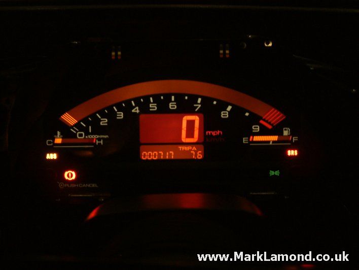
I've developed a flexible fully functional multi-tier menu system that can be displayed in variety of ways depending on the displayed gauge theme (currently only a S2000 style display). This allows me to change between gauge styles, color schemes, data providers (e.g. a debugging provider returning random values for things or my OBDLink data provider for real data). I can also change a variety of settings for the application and gauges in general (e.g. redline, speed alert, audible warnings etc...) I've included some pictures of the menu in action for the S2000 style cluster below.


Indicator Lamps
You might also notice the hazard lights, I've now got a fully functional set of indicator lamps for things like the indicators/hazard lights, ABS, TCS, Engine Check, Battery etc... These can only really be powered by CAN data and not OBD data as most of these things are not accessible via OBD requests (Except for the engine check).

Unit Testing
I had been debating in my mind as to the importance and need of unit testing for a project developed by a single programmer. For small applications it isn't really needed but my application is growing at an alarming rate. At last count (two weeks ago) I had 100 individual class files each performing separate logic. With that much code there is bound to be bugs and things I've missed... So after a few discussions with some colleges at work I decided that it's worth the effort and would probably save me time in the long run by writing tests for all of my code.

Unit testing can be difficult when things are not developed to be easily testable, using techniques such as  TDD / Test Driven Development greatly simplify things. However the idea with TDD is to write the test BEFORE you write your code! So quite a bit of code missed the boat. I've also been using the MVP / Model View Presenter design pattern which lends itself well to being easily tested. The idea here is that the display, processing and data storage responsibilities are separated into their own classes. This for one makes it very easy to have multiple cluster styles as all that is required is a new view (which is based on an interface anyways).

So for new code I will use TDD where possible and for testing the existing code I've been using a combination of NUinit and Rhino Mocks. Both free testing frameworks that work in very different ways. NUinit allows is a framework that allows the creation of standardised classes for testing, because it is so widely used there are lots of free tools that allow you to execute tests from directly in the visual studio IDE. Tests can also be run from continuous integration servers (a server that constantly compiles a projects code based and executes the tests on that code when changes are detected). With NUinit tests you basically write a method that checks and compares values against expected values. Rather simple but when used correctly very effective.


Rhino Mocks on the other hand is a framework that allows classes to be mocked and stubbed. Instead of having to write stubbed implementations of class dependencies you can actually stub individual methods on mocks of those classes. So for instance if you want a method on a class dependency to return a certain value maybe from a database without having to hit the database you can simple stub that method and test the code your specifically targeting.

Sounds like a lot of work? Well it is and it isn't. It's very time consuming but it's much easier to write a test for a specific scenario than it is to find an issue on a production system with a very limited user input system (e.g. a digital instrument cluster with four buttons to drive an entire OS). So the three to four weeks of writing tests spent now should mean less head aches down the road!

Other Stuff (CAN Standards and Chassis Arrival)
I've been in contact with a few sources over the last month who have provided me with some valuable details on how CAN systems are meant to talk to each other and identifiers of standard CAN components. Once I've collated all of these details into a neat package I will make another post in regards to this as it really warrants it's own post.

My shipping agent has contacted me and my Westfield SEiw chassis has arrived at the docks. I'm still going through the customs process so it will probably be later this week when I receive the chassis. There will definitely be some photos up here when I do!

I've also had some interest in me posting some source code for the program I wrote to reverse engineer CAN messages (original post). I will make another post over the next few days with some of the code used for this program.

Wednesday, February 3, 2010

Digital Instrument Cluster Development

Since my last post I've been spending most of my spare time developing the software for my digital instrument cluster. I started this over the christmas break by mocking up a Honda S2000 style cluster. This required quite a bit of math that even if I paid attention in trigonometry in school I probably still never would have remembered. But after some pain and headaches I was able to get something that looked somewhat like a Honda S2000 cluster.

Over the last few weeks I have extended this basic screen into a fully working application using the model/view/presenter development design pattern which for what I am doing makes adding new cluster designs, data providers and logic very simple. Think of is a a plug and play system with lots of small components that can easily be interchanged without rewritting software.

I've added three color schemes to the S2000 cluster based on some color designs that Qube Engineering actually make for the real Honda cluster. Here are some samples of the computer based cluster images and below them their originals.


Because I dont have a working Mazda CAN bus system (still collecting parts for the RX8 to get the system working, they should arrive by Friday I hope) I have been using my fiance's Toyota Echo for testing using generic OBD-II (on board diagnostics) port to obtain the data needed for display on a cluster. The problem with this is that I have to query the car for this data and I can only get between 4-6 responses from the car per second so data isn't displayed all that fast. On a CAN bus system I can get hundreds of packets of data in a second so data display will be in real time (the cluster on CAN equiped vehicles uses the exact same data) and in essence be getting the data from the source. The other benefit of the CAN bus is that I am able to obtain information that simply isn't available via diagnostic commands such as when the indicators are on, handbrake is up, brakes are active and quite a lot more.

I've recorded and uploaded two live test runs videos. The first one is a very short test run showing a few more revs, while the second one is recorded in peak hour traffic leaving the city.

Both of the recordings show the following data:
  • Vehicle Speed
  • Engine RPM
  • Coolant Temperature Gauge
  • Intake Air Temperature (Top left hand side of the info box)
  • Current time
  • Coolant Temperature (Top right of the info box prefixed by 'w')
  • Odometer (Bottom left of the info box)
  • Selected Gear (Calculated based on known gear ratios, engine rpm and vehicle speed)
  • Trip Meter A (Bottom right of info box)
The odometer and trip meters are also a calculated value based on the vehicle speed. After some live testing I noticed that they seemed to read a little higher than the cars on board trip meter. I expectED inconsistencies because of the lag in data coming from the OBD requests but I thought I would see how they both compared to a GPS odometer on a clear day. It turns out after 30km of highway/city driving my odometer was about ~50m more than the GPS unit, whereas the cars odometer was ~500m less than the GPS unit. Some more testing in a car with better electronics will be needed to triple check everything but from what I can see the odometer I wrote is actually quite accurate! Nice...

Down the track once I have a working dash running from CAN data I will add some more gadgets such as GPS navigation (basic and driven from google maps like xGPS) combined with an accelerometer (probably from a Wiimote normaly used for a Nintendo Wii) and digital compass. With these combined I should be able to make a halfway decent navigation system that knows which way my car is facing at a standstill. This will also double as a data logger and lap timer for when I race on the track.

So I will know gear, speed, revs, g-forces etc for every single point I am on the race track. A display like what you can get on popular racing games like Gran Turismo shouldn't be to hard to acheive either!

I do have a few other things in the works for the cluster such as a better design based on a Lexus but I will save that for another post once I have made the software more reliable and robust. Until then....

Friday, January 8, 2010

Delayed Delivery from Westfield

I just found out that the delivery of my clubman chassis is going to be delayed until proably the start of March. A time when I really wont have much time for building a car as I will be getting married!

So I've refocused the project and decided to pull the development of my electronic/computer dashboard closer and do it now :-) I kind of splurged and bought an ASUS 1gb GTS 250 graphics car, two 22" widescreen HD monitors, a Seagate Barracuda 1.5tb hard drive and a new desk as the coffee table just didnt cut it anymore. While a little bit of overkill this will make development of the dash quite pain free. The new setup looks a little like this, I might even try to get the old monitor going too. Yes, yes very geeky... But what can I say? I am a software developer anyways!


I've also decided to bring the rebuilding of the RX8 engine forward too, two months should be plenty of time to do that and also get the dash software looking pretty slick. I am probably going to do at least two dash designs. One will be a Honda S2000 looking dash and the other will have to be an RX8 one. I should have some decent screen shots pretty soon... Stay tuned!

The CAN Bus and loom developments

I spent most of my time off over the break working on still identifying the remaining plugs on the RX8 loom. I've got it to about 90% now and will have a few extra components delivered soon such as the Fuel Pump/Sender, ABS unit/computer, RX8 Instrument Cluster and a few switches for the dash. Unfortunately I need the computer from the dash to interperet the fuel level signal and possibly to also get the trip computer information. I should be able to make it a bit smaller than it is in this picture.


I also spent some time removing the non-standard things I found in the loom such as parts of an alarm. Whats really confusing though is it looks like some of the wiring going into one of the boxes picture below was coming directly out of the ignition switch plug and appears to be standard wiring but the connectors going into the same box on the other side are spliced into the loom with connectors one might find at a local electronics store...


Because I've identified most of the plugs on the loom I thought it was about time to buy myself a cheap battery and get some power to the loom and see if it works. I did find some damaged wires in the engine loom which were pretty easy to fix. But it seems that one of the horns and ABS sensors were too badly damaged and cut out of the loom before I got it :-( I was able to work out what the wires were at least.


One of the other things I did over the break was develop a program to listen to CAN bus messages on a car equipped with a OBD II port that speaks CAN bus. I was lucky enough to borrow a friends Mazda 2 for this. The program I developed allows me to filter messages, translate the bits of the messages into a number of data types and also perform a formula on this value to get a real world figure such as RPM, Speed etc. All of this can be done while receiving CAN messages and the data can be exported to be viewed later.

Currently the program works with the OBDLink tool I bought recently which translates the CAN headers for me. However the program was initially develop to read unproccessed CAN messages so in theory the application should work with any CAN receiver on a COM port with minor changes. If anyone is interested in a copy then let me know, I will try to find a way to put it up in blogger over the next few days. Here is a screen shot of the app...